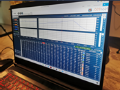
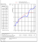
How much sound can your walls block? With STC testing in Field Sound Transmission Class measurement
In addition to the wall STC test performed in the testing laboratory, By using a standard ASTM E90 or ISO 140 eye test or building a mock up test, we can also provide onsite acoustics testing services for rooms that have already been built. This is known as the Field STC test in accordance with ASTM E336 or ISO 140-4, where the field STC test value is usually low. Than the results of the STC tested from the laboratory This is due to the fact that laboratory testing has completely eliminated the factor causing flanking transmission, known as flanking noise. This is different from the actual installation location where there is still a flanking transmission factor.
Test in the laboratory and the room where everything was installed is complete. Geonoise (Thailand) Co., Ltd. offers all types of sound testing services by modern and international standards And give advice that is technically correct by the audio engineer directly
Malaysian man apologises for making 11 speed bumps near his home
BESUT (THE STAR/ASIA NEWS NETWORK) – A man who illegally installed 11 asphalt speed bumps on the street next to his house in Kampung Padang Luas, Jertih, has apologised for his action.
Mr Nor Muhamad Roslam Harun, 40, admitted his mistake in building so many speed bumps on a 40m stretch and causing a hassle to other residents.
“Police officers came to see me on Wednesday morning and asked me to remove all the speed bumps that I had installed.
“So I hired a bulldozer operator to remove all the speed bumps on the street, including the two original ones,” he told Bernama.
The case went viral on social media a few days ago after a man uploaded a picture of the “new speed bumps” on the street leading to his house, which he claimed had been installed by his neighbour.
Mr Nor Muhamad said he installed the speed bumps because he was often disturbed by the noise of passing vehicles.
“The noise from cars and motorcycles disrupts my sleep. I’m so stressed out and I also have other health issues.
“Actually, I wanted to make speed ‘humps’, but the asphalt hardened so quickly before they could be flattened, causing them to become bumps.
“This made the road inaccessible to all cars except four-wheel drives,” he said.
Mr Nor Muhamad revealed that he spent RM1,080 (S$355) of his Employees Provident Fund i-Sinar money to install the speed bumps.
The first DIY noise monitoring, easy to use and install, just plug in the power, wifi and ready to go, online data noise monitoring, accurate, calibrated, weatherproof. Automated alarms by email or messenger.
Noisy neighbours, noise from entertainment or from a factory, road noise?
Register the noise and discuss with the authorities how to resolve the issue.
SpotNoise noise monitoring from the Netherlands, now available via Geonoise Thailand for South East Asia.
Noise Nuisance Monitoring Thailand, Malaysia, Indonesia, Vietnam
The team of researchers from the Centre for Metamaterial Research and Innovation at the University of Exeter used devices, known as thermophones, to create a fully controlled array from just a thin metal film attached to some metal wires.
The results, published in Science Advances, could pave the way for a new generation of sound technology, including home cinema systems.
Traditionally, arrays have been used in a host of every day applications, including ultrasound and sound systems. Arrays allow sounds from several sources to be ‘steered’ in a certain direction, to gain greater control and clarity of the sound produced.
Conventional speaker arrays rely on the production of sound through driven movement of some object — such as a speaker cone. The new study, however, pioneers arrays of speakers that produce sound entirely by heat: thermophones.
Although thermophones have been in existence for more than 100 years, they have, until now, had limited real-world application. However, they have a host of advantages from their mechanical counterparts — including no moving parts and the ability to be mass produced from inexpensive, sustainable materials.
Crucially, they can even be made transparent and flexible, which is desirable for the new wave of flexible technologies being produced.
For the study, the researchers found that, when combined into an array, thermophones are able to reproduce the same control over sound fields as traditional arrays.
However, they do much more than this: as they are driven by electrical currents, the sound they produce mirrors the subtle movement of the current carriers as they flow through the device and, as a result, they create a much richer sound field than traditional arrays.
The researchers suggest that the study opens a route to radically simplify array design, showing that with thermophone technology, it is possible to create a fully controlled array from nothing more than a thin metal film attached to some metal wires.
David Tatnell, lead author of the study and a PhD researchers at the EPSRC Centre for Doctoral Training in Metamaterials said: “Using heat to produce sound is a game changer as it allows us to make speaker arrays smaller than ever before. This, as well as the ability to make the speakers flexible and transparent, has a lot of exciting potential applications, such as haptic feedback systems in smartphones and other wearables.
The shape of the room defines the movement of the sound waves within the room. Placement of acoustic materials should be determined by the way the sound moves in that particular room in order to ensure optimal efficiency of the materials.
1. NARROW ROOMS
Placing the sound absorbing materials on the ceiling in a narrow room will not create the wanted acoustic effect.
Sound absorbers must be placed as close to the sound source as possible. Therefore, the absorbing materials must primarily be placed on the walls
2.ROUND ROOMS
The sound moves towards the constructive centre thereby creating echoes.
The sound diffusing elements should be placed on the curved surfaces in order for the sound to be dispersed in many directions.
3.1 LARGE ROOMS WITH LOW CEILING
In large rooms the sound spreading is experienced as the greatest challenge, since the speech sounds can be heard over long distances.
Sound absorbing and sound diffusing materials should be used, and sound barriers should be applied to the ceiling. The sound regulation from the floor is secured by furniture and the use of sound barriers.
3.2. LARGE ROOMS WITH HIGH CEILING
The acoustic environment in large rooms is sometimes experienced as the one at a railway station. This is partially connected to the fact that it is difficult to concentrate due to the relatively high noise level. Another reason for this is the fact that the conversation over short distances is impeded due to the sound being masked or drowned by the surrounding noise
It is therefore important that all the available surfaces are equipped with effective sound absorbers and sound diffusers. The furniture along with the sound barriers play a highly active role by diffusing the sound and thereby making the existing sound absorbers and diffusers even more efficient.
4. SMALL ROOM WITH PARALLEL WALLS
In small rooms, the low frequencies often seem to be predominant. Therefore, the speech appears to consist primarily of humming sounds. Sound absorbers with a low-frequency profile should be used and placed on the ceiling surface.
5. CEILING DOMES
The sound diffusing elements should be placed on the curved surfaces in order for the sound to be dispersed in many directions.
6. INCLINED CEILING
Inclined ceilings have both a sound spreading and a sound concentrating effect. In most cases, the sound is concentrated because the sound regulation of the area around the inclined ceiling has not been considered carefully.
The wall area opposite the inclined ceiling should also be equipped with sound absorbing materials. As a principal rule, all surfaces above the normal ceiling height (2.60 m) including the end walls should be equipped with sound absorbers.
7.INCLINED WALLS
Inclined walls have both a sound spreading and sound concentrating effect.
The sound spreading effect is achieved by inclining the wall in proportion to other walls and the ceiling. In general, the walls inclined by more than 6 degrees ensure an excellent sound diffusion. The most effective diffusion is obtained by applying several angles.
8. VAULTED CEILING
In rooms with vaulted ceilings, the sound is concentrated in the constructive centre making the sound appear with a stronger intensity. The sound movements also appear stronger along the curve.
9. CONNECTED ROOMS
Rooms that are linked by a large opening in between, influence each others sound environment. A room without acoustic regulation can act as an echo chamber reinforcing the sound, when connected to an acoustically regulated room.
Both rooms must be equipped with sound absorbers. If the distance between the opening and the opposite walls is short (5-6 m), the walls much be covered with sound absorbers or diffusers.
10. ROOMS WITH MEZZANINE
In rooms with mezzanine, it is possible to create different sound environments in the same room. In the large, open room, an environment with long reverberation time is created. The space above and below the mezzanine has a shorter reverberation time. The challenge posed in this type of rooms is the sound reflection and the harmonization of the different reverberation times.
The wall opposite the mezzanine should be equipped with sound absorbers or diffusers. In addition, sound absorbers should be placed on the underside and the banister of the mezzanine. In order to prevent large differences in the reverberation times between the large room and the space around the mezzanine, sound barriers can be applied.
Credit: KNAUF DANOLINE
Check out our free reverberation online calculator (for basic rooms).
Previously, we have discussed how the human auditory system works and recognizes the sound direction. Now, we will discuss how sound is perceived through our mind. In acoustics, the sound processing into the human auditory system is divided into 2 different mechanisms, namely hearing and listening. Hearing is the process of the mechanism of sound wave propagation into the human auditory system due to the sensitivity of the human auditory system to the vibration of sound waves with a certain frequency and intensity. While listening is a process of hearing along with the interpretation of information about the environment of a place based on the details contained in the vibration of sound waves that are heard.
Interpretation of sound information in the listening process is the vibrations of sound waves that are heard by humans. That not only represents the source of the sound but also contains information about the environment in which the sound is heard due to the physical mechanism that occurs when the sound wave propagates. Listening is considered a complex mechanism because it involves multi-level attention and higher cognitive functions. There are three levels in listening that are used to explain the complexity of listening namely listening-in-search, listening-in-readiness, and background listening.
Listening then forms us in an interpretation and perception in an environment based on its acoustic conditions. For example, if we close our eyes and we are given a stimulus in the form of the sound of water, squeaking, and the sound of wind with a certain level of sound pressure (SPL) we can interpret this as a feeling of being in a park. Then if the sound is added to the vehicle’s sound stimulus with a sufficiently audible sound pressure level, this might disturb the atmosphere of the park, and we feel uncomfortable. The action and interaction of natural factors and / or human factors acoustically in a place is called soundscape. This is because the sound in the environment does not only focus on a person, but also how one interacts with the sound and how one’s attention to the sound that arises.
Simple soundscape involves the type of sound source, location related to activities that occur in the related environment, environmental conditions and various subjective things that shape one’s perception and interpretation. This relates to the definition of soundscape in building one’s perception where it is also influenced by their socio-cultural and also the soundscape approach is seen from various disciplines.The soundscape process can be seen in the process diagram in Figure 1.
The analysis of soundscape can produce information for the basis for taking action in the form of sound management, which is to sort out what sounds should be heard and what sounds should be covered with other sounds (masking noise), by directing the attention of visitors to certain sounds that are in line with expectations they are based on the function of the related place.
Written by:
Adetia Alfadenata
Acoustic Engineer
Geonoise Indonesia
support.id@geonoise.asia
References :
1. B. Truax, Acoustic Communication. Ablex Publishi, 1984
2. A. Ozcevik and Z. Y. Can, “A Field Study on The Subjective Evaluation of Soundscape,” in Acoustics 2012, 2012, no. April, pp. 2121–2126.
3. F. Aletta and J. Kang, “Soundscape descriptors and a conceptual framework for developing predictive soundscape models,” no. October 2017, 2016.
The British Standards Institution, “BS ISO 12913-1:2014 – Acoustics — Soundscape Part 1 : Definition and conceptual framework,” ISO, 2014.
5. D. Botteldooren, C. Lavandier, and A. Preis, “Understanding urban and natural soundscapes,” in Forum Acusticum 2011, 2011, vol. 1, no. c, pp. 2047–2052.
Many around the world are experiencing life with very low noise levels due to restrictions as we are confined to our home and there is a decrease in the industrial, transportation and leisure activity. This provides a wonderful opportunity to quantify and record for the future the lower noise levels of our soundscapes. With the reduction in shipping there is also a change in the underwater soundscapes.
Nowadays there are a high number of noise monitoring systems (noise monitoring terminals, city wide systems, underwater systems etc.) installed all over the world which will capture this information for the future. However, there are many acousticians working from home with access to a sound level meter that can be used to capture the soundscape from their balcony or from their garden and compare the before and after the restrictions.
The IYS 2020 committee has provided a central contact between a number around the world who were thinking similarly that there would be some benefit in coordination and a little standardization in the capture of the data. Marçal Serra from CESVA has taken a lead to set up a LinkedIn group COVID-19 Noise Reduction (at www.linkedin.com/groups/13844820/) and with hashtag #COVID19NoiseReduction for any posts.
The following is a general structure for those who wish to participate and share their data in the future. But do not break your confinement to report this data!
Place: Country and city (e.g., Spain village near Barcelona)
Primary noise source: (e.g., Traffic noise: note number of lanes per direction or Social noise: note if café/bar/restaurant/sporting)
Noise measuring system: The noise measuring system used to measure Lduring, Lbefore, and Lafter
Noise level during COVID-19 confinement:Lduring, expressed as a weighted overall level (preferably LAeq,1 hour), spectrum or psychoacoustic metrics as Loudness. It could also be reported as an image of the noise time history or a weekly color map and/or compiled into a report/article/conference paper with the measurement details and the comparison data
Noise level before & after COVID-19 confinement:Lbefore & Lafter, expressed in the same way as Lduring and over the same time period.
Most industrial activities create noise that can be harmful to the environment as well as to their workers. To minimize this effect, governments, associations, and companies have created regulations, standards, and codes to set the allowable noise both inside the sites, that can be harmful to the workers, as well as to the environment. In a lot of cases, during the planning phase, the plant owner and project management want to be sure that the noise levels are acceptable. Since the plant is not built yet, what can be done is creating a noise model to simulate the plant, so that the noise levels can be predicted. In this article, we will explore how we can do so.
The first thing we must know is how much noise does the noise sources inside of the plant will emit. The noise source is usually described in two ways which is Sound Power Level (Lw or SWL), and Sound Pressure Level (Lp or SPL) in certain distance, most commonly Lp in 1 m distance. There are multiple ways to get this information for certain noise sources. First, if the equipment type and model have been chosen, the equipment manufacturer will normally report the noise level in their datasheet. However, this is not usually the case with most of noise predictions since the noise study is normally done before the equipment suppliers are appointed. So, the second way to be able to predict the noise emission is by following empirical formulas that are developed by researchers. You can find such formulas in some textbooks, journals, and papers. For rotating parts, you will need its rated power and rotational speed to be able to estimate the noise emission.
For example, in the speed range of 3000-3600 rpm, the noise level of a pump with drive motor power above 75 kW can be predicted using the following equation:
Suppose a pump with rotational speed of 3000 rpm and 100 kW, according to the formula, it can be estimated that the noise level at 1 m from the pump would be 92 dB. And suppose the noise source can be considered as point source on the ground (hemisphere propagation), the sound power level of the pump can be calculated using the following formula:
Where r is the distance from source to receiver
And in this case, the predicted Lw would be 100 dB.
Thirds, noise measurement to a similar equipment can also be an option to be able to determine the noise level of the new equipment. Another option, in some countries, there are noise emission limit for certain equipment, you can use that limit if it is applicable for your project.
After the Lw of all noise sources is obtained, we want to calculate the noise levels (the Lp) at the receivers. There are some standards which procedure can be followed to calculate this. Few of which are ISO 9613-2, NORD 2000, CNOSSOS EU, and many others. Most of the standards consider some factors to the calculation such as distance, atmospheric absorption, ground reflection, screening effect (from barriers and obstacles) and other factors such as volume absorption from vegetation, industrial site, etc. Most consultants and projects will require a software such as SoundPLAN to do this calculation.
Depending the project, there are few types of noise limit which compliance will need to be ensured. The most common ones are environmental noise limit, noise exposure limit, area noise limit and absolute noise limit. Besides, the noise level during emergency is also modelled so that the information can be used for safety and PAGA (Public Address and General Alarm) study.
Environmental noise limit is usually calculated for the plant’s contribution to the plant’s boundary as well as to the nearest sensitive receiver such as residential and school near the plant. How this is accessed depends on the regulation applicable on the plant area. In Indonesia for example, the noise limit for residential area is Lsm 55 dBA and industrial area is Lsm 70 dBA. Lsm is a measure like Ldn, but the night noise level addition is 5 dB instead of the 10 dB addition that most other countries, especially Europeans use. To ensure compliance with this regulation, the noise level at fence should be less than Lsm 70 dBA, and suppose there is a residential area nearby, the contribution from the site should be less than 55 dBA. It is also advisable to measure the existing noise level at the sensitive receivers to make the study more relevant to the situation.
Noise exposure limit is the maximum exposure to noise that the workers get during their working period. In Indonesia, the noise exposure limit is 85 dBA for 8 working hours. To change the working hours, 3 dB exchange rate is used. For example, if the noise level in the plant is 88 dBA, then the workers can only work there for 4 hours, if it is 91 dBA, then the time limit is 2 hours, and so on. To extend the working hours on a noisy area, the options are to actually reduce the noise level by reducing the noise emission from the source or noise control at transmission (for example using barrier), or by usage of Hearing Protection Device (HPD) for the workers such as ear plugs and ear muffs. The noise exposure of workers after usage of HPD can be calculated using the following formula:
Where NRR is the noise reduction rating of the HPD in dB.
Different area might have different noise level limits, and therefore area noise limits are useful. For example, in an unmanned mechanical room, the noise level can be high, for instance 110 dBA. However, inside of the site office, the allowable noise level is much lower, for example 50 dBA. This noise level shall be calculated to ensure compliance with the noise limit. Different companies might have different limits for this to ensure their employees’ health and productivity. If the area is indoor and the noise source is outdoor, then the interior noise level can be estimated using standards such as ISO 12354-3.
The absolute noise limit is the highest noise level allowable at the plant, and shall not be exceeded at any times, including emergency. In most cases, the absolute noise limit for impulsive sound is 140 dBA. To ensure compliance with this requirement, potential high-level noise shall be calculated, for example safety valves.
During emergency, different noise sources than normal situation will be activated, such as flare, blowdown valves, fire pumps, and other equipment. In such cases, the sound from the alarm and Public Address system must be able to be heard by the workers inside of the plant. Normally the target for the SPL from the PAGA system should be higher than 10 dB above the noise level. Therefore, the noise level during emergency in each area should be well-known.